- Published: 2024-09-03
- Categories: Kkajeong
- Tags: dxf, dxf double lines, kicad
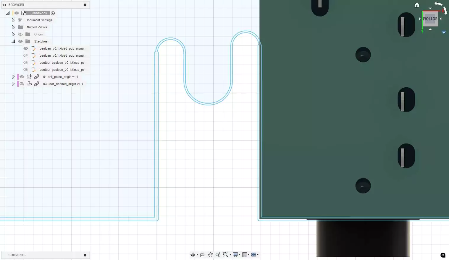
Kicad에서 힘들게 PCB를 설계하고 나서, 케이스를 만들기 위해서 DXF파일로 Export하고 난 후 Fusion 360에서 확인 해 보니 그림과 같이 라인이 2개가 생성되어서 케이스를 만들기 어려운 경우가 발생 했습니다.
검색을 해보니 이는 "DXF Options > Plot graphic items using their contours" 옵션 선택의 문제였습니다.
"Plot graphic items using their contours" 사용 했을 경우
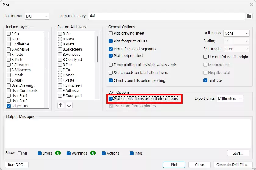
"Plot graphic items using their contours"에 체크하고 DXF Export한 파일은 Fusion360에서 위와 같이 두 줄로 나타납니다.
Plot graphic items using their contours 사용 하지 않을 경우
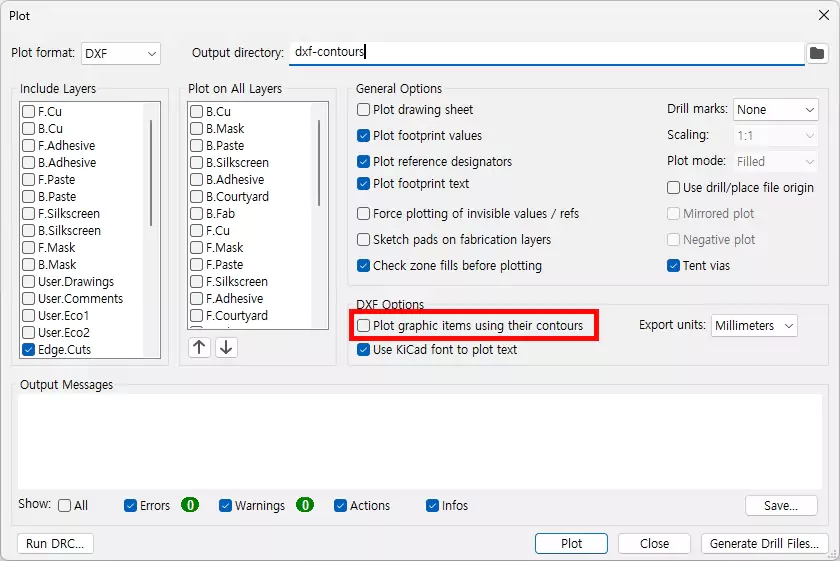
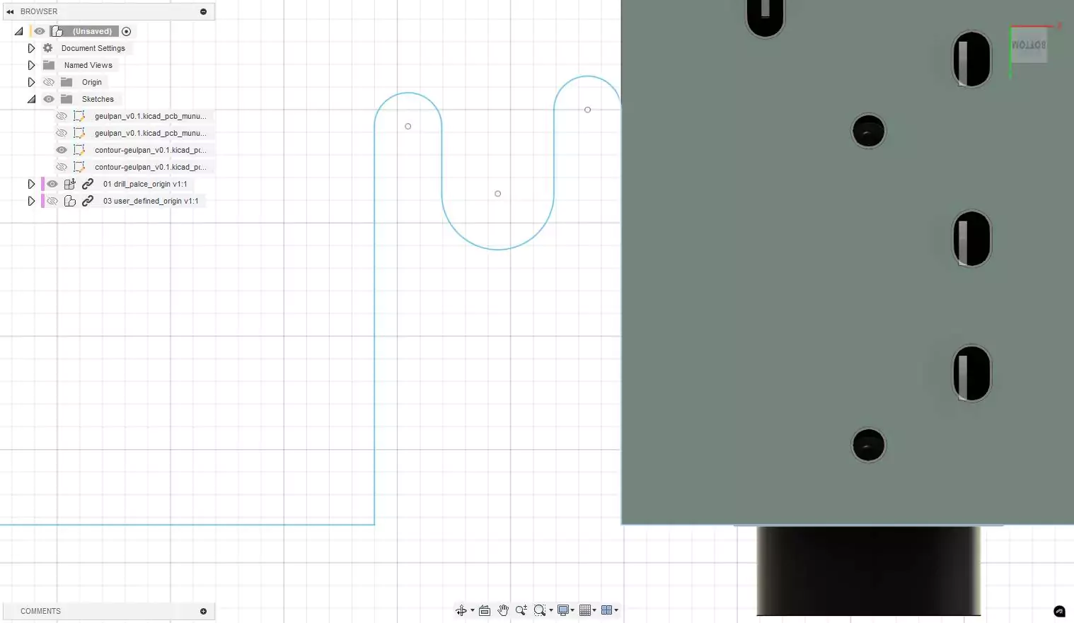
"Plot graphic items using their contours"에 체크 해제하고 DXF Export한 파일은 Fusion360에서 위와 같이 한 줄로 나타납니다.